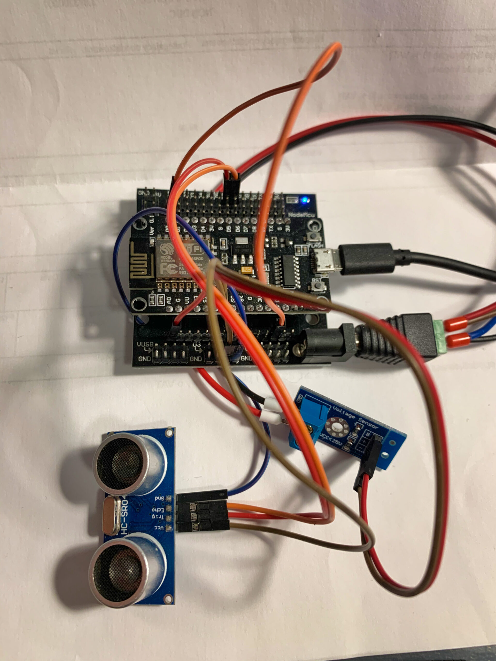
NodeMcu (ESP8266) Water Level Monitor With a Voltage Sensor
This subject in the theory looks very easy. Just get NodeMcu board, plug sensor from the family of sensors (HY-SRF05, HC-SR04), some kind of voltage sensor and we are good to go. But you can get couple of unexpected issues here. Let’s start from the NodeMcu unit. It’s specific.
Weird NodeMcu PIN arrangement
First thing first pins on the board doesn’t match pins in the code. I mean – addressing is not se straight forward like in regular Arduino boards. Here is a official mapping of pin outs .

A little bit of helper code:
#define PIN_WIRE_SDA (4)
#define PIN_WIRE_SCL (5)

static const uint8_t SDA = PIN_WIRE_SDA;
static const uint8_t SCL = PIN_WIRE_SCL;

static const uint8_t LED_BUILTIN = 16;
static const uint8_t BUILTIN_LED = 16;

static const uint8_t D0   = 16;
static const uint8_t D1   = 5;
static const uint8_t D2   = 4;
static const uint8_t D3   = 0;
static const uint8_t D4   = 2;
static const uint8_t D5   = 14;
static const uint8_t D6   = 12;
static const uint8_t D7   = 13;
static const uint8_t D8   = 15;
static const uint8_t D9   = 3;
static const uint8_t D10 = 1;
It’s good to have something to map them according to “regular” naming – so do whenever i have to use digital pin D0 – use D0 instead of trying to guess 16 and so on.
Reserved Pins
You don’t hear about it often, but for example pins D3 & D4 (GPIO2 and GPIO0) need to be both HIGH to boot in normal execution mode. What’s the isse then ? When I hooked my HC-SR04 to this pins it provides LOW in idle state – so my board didn’t boot. Solution – move on to higher pins.
Voltage Sensor calculations
Every other example found in the web gives these calculations:
const int voltageSensor = A0;

float vOUT = 0.0;
float vIN = 0.0;
float R1 = 30000.0;
float R2 = 7500.0;
int value = 0;

value = analogRead(voltageSensor);
vOUT = (value * 5.0) / 1024.0;
vIN = vOUT / (R2/(R1+R2));
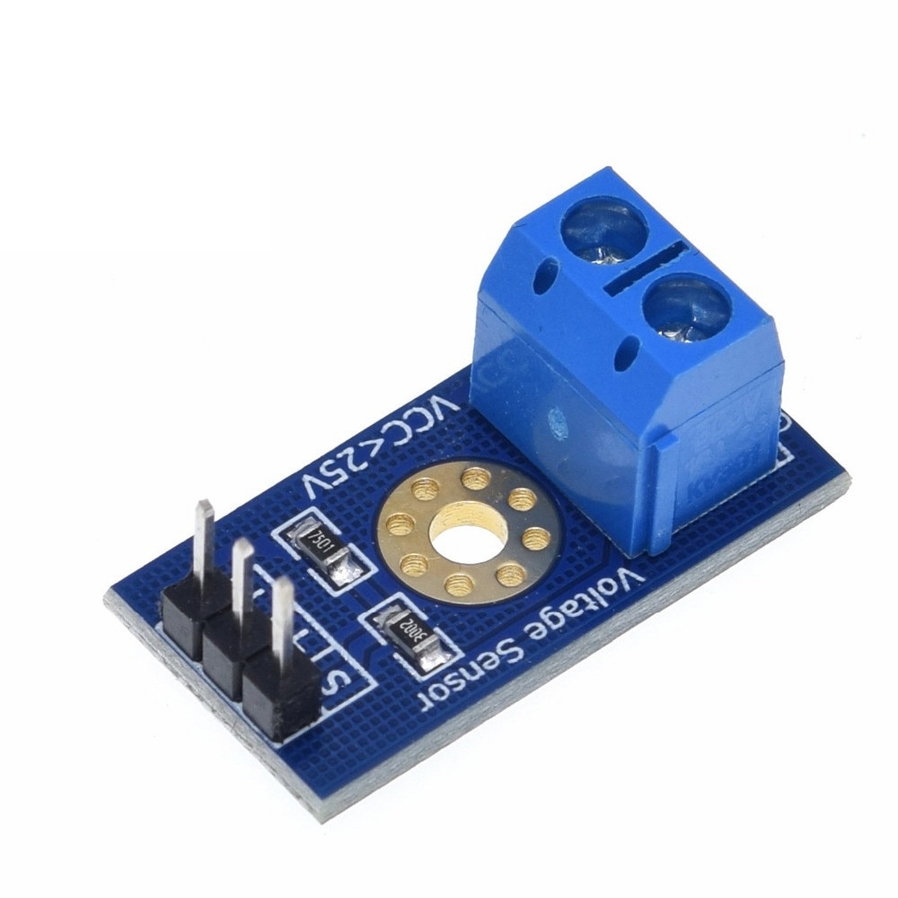
Without going into to much details – we do have value of resistors here (R1, R2) and then magic formulas vOUT and vIN – nobody mentions that magical number 5.0 is not random… it’s reverence value of your board. So 5.0 it’s good for regular Arduino board powered by 5.0V but not so good for NodeMcu which has 3.3V…
Powering whole module
NodeMcu will be happy with 3.3V but HC-SR04 needs a little bit more. Power your sensor with 5V – otherwise your distance sensor wont work correctly.
And also – not sure how frequent you need your data to be updated, but small batter won’t stand to long. We have to save some energy. The easiest way to save the juice is to use sleep mode for out board.
There are four types of sleep modes for the ESP8266: No-sleep, Modem-sleep, Light-sleep, and Deep-sleep.

I wouldn’t bother with anything then deep-sleep. There is a small requirement – If you use the deep sleep mode, you have to connect D0 with RST on the ESP8266 NodeMCU. You can find a lot of good articles around this subject. So our goal is to sleep most of the time. We just need check every now and then water level, and batter level. Send results to out collector service and go back to sleep to preserve energy.
So finally I end up with code bellow. Let me know if you have any questions.